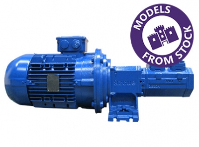
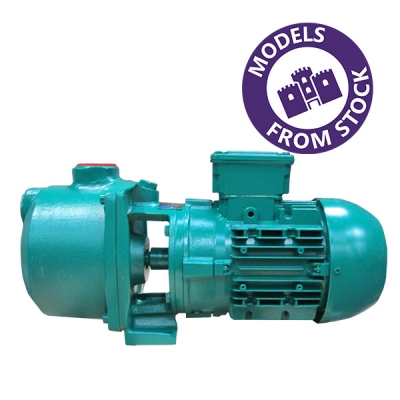
MODELS AVAILABLE FROM STOCK Shorter lead times. Your deadlines met.
APPLICATION EXPERIENCE YOU CAN RELY ON We'll specify the ideal solution for your process.
LOWER TOTAL LIFETIME COST SOLUTIONS Efficient, easy to maintain & long life design.
It is no secret that with the vast range of pumping technologies, performance ranges and applications, selecting a pump for your requirements can be a confusing topic. This is where Castle Pumps exceeds your average pump supplier and add their value to your enquiry. Our technical sales engineers have extensive experience in specifying the ideal pump for your requirements, meaning there is a high probability that one of our engineers has already solved your pumping problem whilst helping another client just like you over our 15 years in the market. Send us your enquiry today.

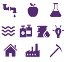
If you're in the marine, power generation, manufacturing, agriculture, food & drink, oil & gas, chemical, waste water or pharmaceutical industries - then our customer base includes companies just like you! We provide industry-specific solutions for your applications involving fuels, water and lubricants to name a few.
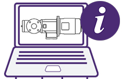
Do you specify, procure, maintain or even just use pumps? If yes to any of those, then you'll find the Info Hub a wealth of knowledge! Continuously updated with information from guides to sourcing a pump to maintenance schedule tips, it's worth a read!
If you're in the marine, power generation, manufacturing, agriculture, food & drink, oil & gas, chemical, waste water or pharmaceutical industries - then our customer base includes companies just like you! We provide industry-specific solutions for your applications involving fuels, water and lubricants to name a few.
Do you specify, procure, maintain or even just use pumps? If yes to any of those, then you'll find the Info Hub a wealth of knowledge! Continuously updated with information from guides to sourcing a pump to maintenance schedule tips, it's worth a read!
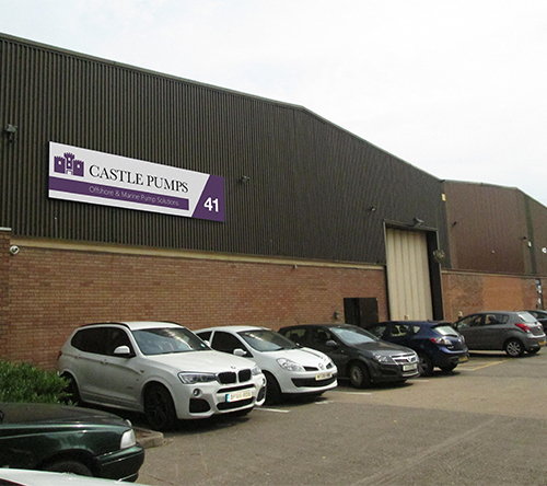
Castle Pumps Ltd are a specialist pump supplier for the marine and industrial markets for most applications involving water, fuels and lubricants. Assured quality, technical expertise and application experience is what you can expect. Our added value is our knowledge in specifying the right pump for your requirements.
As the UK agent and stockist for Spanish manufacturer Azcue Pumps, you can buy in confidence thanks to their long life pump design, 100% pump testing regime, available complete with witness testing from an approved accreditation body if required and interchangeable spare parts that are available for a guaranteed 15 years.
Castle Pumps are fully accredited by BSI to ISO 9001 and ISO 14001.
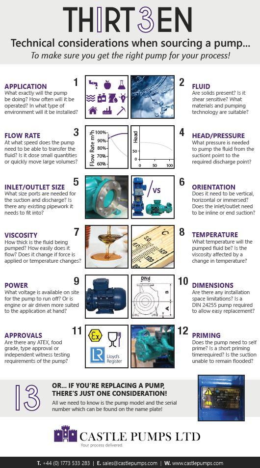
Sourcing a pump and sourcing the RIGHT pump for your process is completely different. A pump may do the job, but if the application is pushing its capabilities, it will operate less efficiently and its lifespan will reduce, ultimately costing you money!
Here's our quick guide to the 13 technical considerations that are typically requested to specify the best pumping solution. You may not know all the answers, but the more information you can provide us with the better. We’ll do the rest…
![]()
Castle Pumps are fully accredited to enable you to buy with confidence. Our accreditation includes:
![]() A division of the CTS Group, Part of Flow Max Ltd.
A division of the CTS Group, Part of Flow Max Ltd.