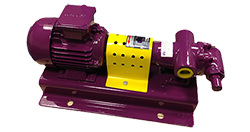
How does a gear pump work?
Gear pumps are one of the most common types of positive displacement pump. They operate by an unchanging volume of fluid passing between the teeth of two meshing gears and their casing at a constant rate (not between the gears themselves). As the gears rotate and the meshed teeth separate, a partial vacuum is formed that fills with fluid. As the gears continue to rotate, they trap the liquid and move it around the casing from the suction to the discharge point.
There are two types of gear pump; external and internal gear pumps. Below is a simple comparison:
| External Gear Pump | Internal Gear Pump |
 |  |
| Two identical gears positioned side by side, rotating into one another. One gear is driven by the motor and in turn moves the other gear. | Operates a “gear within a gear” principle, whereby one gear (the idler) is positioned inside another gear (the rotor). |
| Works to higher pressures. | Works to moderate pressures. |
| Compact construction and less expensive design. | Bulkier construction, more expensive design. |
| For medium/low temperature fluids. | Can handle high temperature fluids. Often supplied with a heating jacket to maintain the fluid temperature |
| Larger outlet sizes and high capacities. | Smaller outlet sizes and higher capacities. |
| Bi-directional if spur gears are selected. | Always bi-directional flow. |
Design benefits
High pressures - High viscosity fluids are able to be pumped over long distances using external gear pumps, thanks to their ability to handle high pressure applications.
Self-priming capabilities – Gear pumps benefit from excelling self-priming capabilities thanks to their rotating gears evacuating any air in the suction line, and forcing the liquid into the pump inlet. This makes gear pumps a suitable solution for applications with difficult suction conditions where the pump may be located considerable above the liquid.
Bi-directional - Internal gear pumps have spur gears, which enable flow in either direction. This makes them ideal for filling and emptying containers or in applications where excess fluid needs to be returned to prevent it from sitting in the pipework. External gear pumps are usually available with either spur gears, making them too bi-directional, or herringbone gears, which are for particularly viscous fluids but do not allow reversible flow.
Steady and pulse-less flow – Both types, but in particular internal gear pumps, provide a smooth, constant flow as their gears roll in the same direction without interrupting the liquid flow. The tight internal clearances between the gear teeth and the pump casing allow very precise volumes of fluid to pass for each gear revolution. This ensures a reliable, steady output of fluid passes through which is required for accurate metering.
Typical applications of a gear pump
Gear pumps are one of the most common pump types for the handling of clean oil and other self-lubricating, high viscosity liquids such as paints and soaps in relatively high pressure installations. Thanks to their tight internal clearances and positive displacement operation, external gear pumps in particular benefit from a more reliable measure of the fluid that has passed through, making them ideal for batching applications. Internal gear pumps are able to handle high temperature fluids such as thermal oil, and can be supplied with an external jacket to maintain the temperature level.

Applications that gear pumps are commonly used within include:
- Automotive, lube and fuel oils
- Hydraulic applications
- Paint and ink
- Resins, adhesives and polymers
- Pulp, lime and lye
- Small scale hot oil circulation
- Liquid soap
Whilst suitable for relatively thick oils, they are typically only suited to clean, non-abrasive liquids that are free of solids due to the meshing gears. If solids make it into the tight clearances between the gears they can result in immediate wear and a reduced pump lifespan.
Low viscosity fluids should also generally be avoided, particularly with internal gear pumps, as they can cause the fluid to leak backwards or “slip” through the tight spaces from the high pressure discharge side back to the lower pressure suction side. This can cause reduced flow and efficiency.
Operation guidance
Do not run dry – If a gear pump is run dry, the unlubricated gears will rub together causing friction. The heat caused by this friction will cause the gears to expand and begin wearing against the pump casing resulting in damage to the internals. This can also result in the tight tolerances being lost if the gear teeth effectively become chewed up, resulting in backwards flow and lost efficiency.
Operate at maximum speed – Gear pumps struggle to maintain performance at low speeds and flow rates due to their weak volumetric efficiency. Therefore to get the best from their output they need to be operated as close to their maximum rated speeds as they can.
Inspect bearings – Each gear is supported by a shaft which has bearings on either side of the gear; and external gear pump has four bearings and an internal gear pump has two. These need to be regularly checked for wear as they are what maintain the balance of the gears.
Check gear clearance – The operation of a gear pump relies on the tight clearances between the teeth and the chamber. A common test to see if there has been wearing is to try and put a piece of paper between the clearances; if it easily passes there is evidence to suspect wear.


