How do progressive cavity pumps work?
Progressive cavity pumps, otherwise referred to as a helical rotor pump, eccentric screw pump or mono pump, are part of the positive displacement family. Positive displacement pumps are characterised by an operation that moves fluid by trapping a fixed volume and forcing that trapped fluid into the discharge pipe.
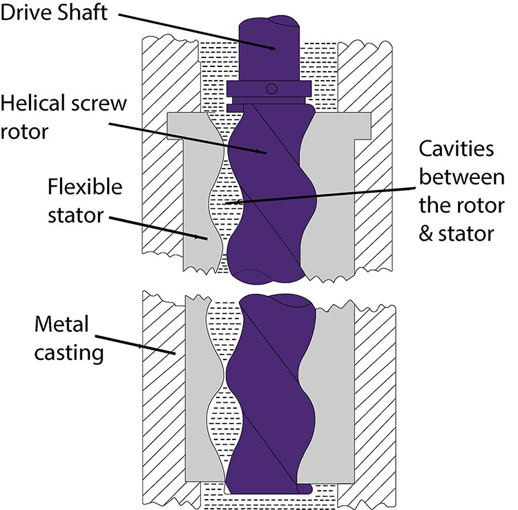
The progressing cavity working principle in particular consists of a spiralled helical rotor (like a cork screw, hence their names eccentric screw pump) that sits tightly inside a rubber stator/sleeve. As the rotor turns inside the stator, it forms a set of fixed-shaped cavities that progress along the length of the stator and force the fluid inside to move along with them as they turn.

Design benefits
Viscous & abrasive fluids - The progressive cavity pump is often seen as a solution when many other types fail thanks to their ability to handle difficult fluids. Its low internal velocity design means that viscous fluids and those containing solids can be handled effectively e.g. sewage, slurries, waste water and food waste. In addition, the stator has some flexibility reducing the wear particles cause as the come into contact. This is this reason why a mono pump is often selected over centrifugal pumps; a design most suited to water or fluids with a similar thickness, or vane and gear pumps that would simply clog with the presence of solids due to their close tolerances.
Smooth, low pulsating flow - As the fluid progresses through the overlapping cavities steadily at a predictable rate, the progressive cavity design benefits from low pulsation pumping. This smooth operation means that in dosing applications, extremely accurate metering can be carried out. Less pulsations in the flow of fluid also limits the amount of stress the other components in the installation are put under.
Low shear operation – Thanks to the low internal velocity compared to other pump designs, the progressing cavity pump results in low levels of shearing being applied to the pumped medium. This makes it ideal for handling shear sensitive products that need to maintain their structure during the pumping process. Examples include food products such as olives, adhesives that may lose their stickiness and water/oil mixes that need to keep the oil droplet sizes intact in order for a separator to work most efficiently. Another example of shear sensitive products are thixotropic fluids; those that are thick when static but become less viscous when shaken, agitated or stirred e.g. tomato ketchup, and rheopectic; those that when agitated become thicker e.g. cream. Thanks to their low RPM and gentle pumping motion, progressing cavity pumps keep agitation of the pumped medium to a minimum.
Constant flow - As a progressive cavity pump is able to produce the same flow rate regardless of the viscosity of the medium being pumped, they are an ideal solution for when a constant flow is required but the thickness of the fluid may be variable.
High pressures – High pressures can be achieved with eccentric screw pumps, ensuring that even difficult to pump fluids can be pump over considerable distances.
Great suction lift capabilities – The progressing cavity mono pump design benefits from a low Net Positive Suction Head (LPSH), which means that less inlet pressure is required for the pump to operate at the required duty point. Consequently, they are a good solution when the suction conditions of an application are not ideal.
Typical applications of a progressing cavity pump
Given the above design benefits, progressive cavity pumps are commonly used, but are in no way limited to the following applications:
- Sewage and sludge pumping
- Dirty waste water
- Bilge water removal
- Viscous chemical pumping
- Shear sensitive products
- Pulp, paper paste and starch handling
- Biomass transfer
- Oil transfer
- Fluid dosing applications

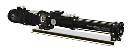
Progressing cavity pumps are identified by their long, thin construction as the stator is often about ten times as long as its width as per the image to the right. This means that generally quite a large amount of space is required within the installation, which is sometimes a drawback. Models are available with a more compact design however this is usually at the cost of the maximum pressures they can work at.
It is important to note that progressive cavity pumps must be selected carefully for the temperature of fluid and are not a good solution where temperatures vary significantly. The stator and helical rotor can sometimes only have a few mm of clearance to enable the pump to be efficient and transfer fluids at the requested flow rate. As the stator is rubber, large temperature fluctuations can cause a slight swelling meaning a difference in efficiency, flow rate and pressure will be experienced. Eccentric screw pumps will be typically sized to the requested flow and pressure at a certain temperature and should this change then it is possible for the pump to still work but at reduced efficiency.
Troubleshooting
Progressive cavity pumps are a robust and reliable design, yet as with anything issues can occur. Should you experience a problem there is a likely explanation which can be identified using the below progressing cavity troubleshooting table.
| A | Pump won't start |
| B | Pump has no suction |
| C | Wrong flow rate |
| D | Uneven flow |
| E | Excessive vibration or noise |
| F | Pump has seized/stopped conveying |
| G | Faulty stator |
| H | Faulty helical rotor |
| I | Seal is leaking |
| J | Drive is generating too much heat |
| K | Insufficient pressure |
| A | B | C | D | E | F | G | H | I | J | K | Possible Problem |
| X | X | Adhesion between helical rotor and stator due to prolonged activity. Lubricate and move the stator with the special tool. | |||||||||
| X | X | X | X | X | X | X | Excessive pressure on pump outlet port. | ||||
| X | X | X | X | X | X | X | Foreign body inside the pump. Disassemble the pump, remove the object and replace any damaged parts. | ||||
| X | X | X | X | X | Expansion of the stator is too high and has blocked the helical rotor. Verify the fluid temperature. | ||||||
| X | X | X | X | X | X | X | Dimension of the solids in the fluid are too big. Reduce the rpm or install a filter at the pump suction. | ||||
| X | X | X | X | X | The product tends to sediment and/or crystallise when the pump is inactive. Flush the pump; disassemble and clean if necessary. | ||||||
| X | X | X | X | Air leakage at suction casing or from the seal. | |||||||
| X | X | X | X | X | Temperature is too low and causing fluid to solidify. Heat the pump | ||||||
| X | X | X | X | X | Verify suction casing, suction head too high or suction head vacuum gauge. Increase inlet section or the filter mesh gauge. Open the intake valves. | ||||||
| X | X | Air inclusions in process liquid. | |||||||||
| X | X | Speed too low with low viscosity liquids and intake sections too big. | |||||||||
| X | X | X | X | X | X | Speed too high with very viscous liquids and intake sections too small. Risk of cavitation. | |||||
| X | X | Wrong rotation direction. Check the data plate and pump specifications. If necessary, invert motor polarity. | |||||||||
| X | X | X | X | Available NPSH inferior to pump demand. Risk of cavitation. | |||||||
| X | X | Verify the movement of the drive shaft. Incorrection positioning of the transmission brush. | |||||||||
| X | X | X | X | X | The pump is running dry, either partially or completely. Replace the stator if faulty. Install a dry run protection probe. | ||||||
| X | X | X | X | X | X | X | Stator faulty or worn. Replace. | ||||
| X | X | X | X | X | X | X | Helical rotor faulty of worn. Replace. | ||||
| X | X | Stator material not suitable. Check the order. | |||||||||
| X | Helical rotor material not suitable. Check the order. | ||||||||||
| X | X | X | A part of the transmission is broken. Worn out or faulty joint. | ||||||||
| X | X | The bearings in the bearing housing or in the drive are no longer suitable. Replace. | |||||||||
| X | X | X | X | X | X | Wrong pump speed. Verify rpm and power absorbed at the motor. Verify frequency and voltage. | |||||
| X | X | X | X | X | X | Viscosity too high. Check with pump specifications. | |||||
| X | X | X | X | X | The gland requires adjustment. Replace and worn parts (rings and hollow shaft). | ||||||
| X | X | Mechanical seal. Check faces and o-ring for wear. Verify seal compression. Replace worn parts. | |||||||||
| X | X | Unsuitable seal system. |


